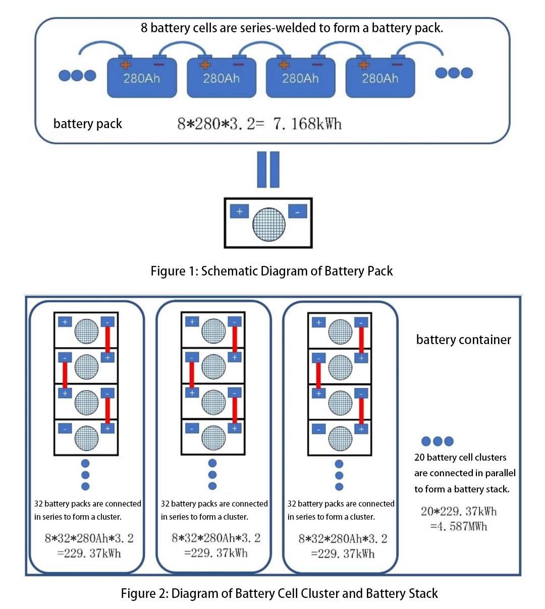
The smallest unit of electrochemical energy storage is the battery cell, taking lithium iron phosphate cells as an example, which have a voltage of 3.2V. Currently, mainstream energy storage cells have capacities ranging from 120Ah to 280Ah. For large-scale electrochemical energy storage systems, the entire architecture can be divided into three parts.
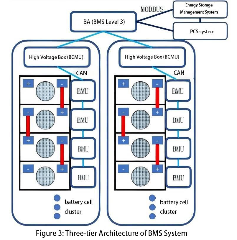
Based on the overall architecture of the battery system, the BMS system architecture corresponds accordingly (see Figure 3). Generally, for large-scale electrochemical energy storage systems, the BMS system is divided into three layers.
Furthermore, the BMU device actively balances the cells inside the pack through balancing harnesses. The balancing current typically ranges from 3A to 5A.
The second layer of control is the Battery Cluster Management Unit (BCMU) for each battery cluster. The BCMU receives voltage and temperature data from each cell within the cluster via CAN communication from the BMU, and also measures the current within the cluster. Additionally, the BCMU unit controls the operation of breakers and contactors inside the high-voltage box based on internal protection parameters. For water-cooled energy storage systems, the BCMU also controls the operation and power of the entire cluster's water-cooling units.
The third layer of control is the Battery Array (BA) system, which collects data from all cells within the entire battery stack. It communicates with the PCS (Power Conversion System) and the backend EMS (Energy Management System) in real-time, uploading cell data to the EMS for monitoring and transmitting relevant alarms and protection actions to the EMS system. In case of emergencies, the BA communicates with the PCS via dry contacts to initiate emergency shutdown.
A robust BMS system generates accurate outputs from inputs under expected operating conditions and environments. External factors may interfere with the BMS's correct outputs, such as environmental temperature affecting State of Charge (SOC) accuracy or contactors not responding correctly to commands. This necessitates a BMS system with strong robustness.
For the software functions of the BMS, they can be divided into device drivers at the lower level, hardware interface programs, and upper-level computational decision-making programs.
For the BMU system, its main function is to collect voltage and temperature data from each cell and upload it to the BCMU. The BMU performs basic logic control, such as monitoring for voltage and temperature out-of-range alarms, and transmitting these alarm signals. The BCMU, as the cluster management unit, utilizes complex algorithms and models to assess the operational status of the cells and further uploads the data to the BA.
The BA should function as a computer equipped with extensive data processing capabilities and configured with a database. It can perform historical data analysis and optimize cell models further. Once optimized, the latest models are sent down to the BCMU unit. Only through such layered control can the BMS meet the requirements for real-time and precise control.
BMS Hardware Section
Hardware Architecture
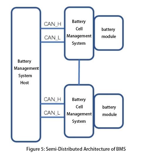
The hardware architecture of large-scale electrochemical energy storage BMS can be divided into two types: distributed architecture and semi-distributed architecture (see Figure 5). Distributed architecture has been discussed in the previous section.
Its main feature is high modularity, and in highly integrated systems in the future, the charging circuit detection may be directly integrated into the battery module. For semi-distributed architecture, the Battery Management Unit (BMU) is responsible for a battery pack and can operate with high-voltage measurement and control equipment. This module may include high-voltage measurement, contactors or relays, fuses, and current sensors or shunts. Such modules make the system easier to scale.
The power supply for the battery management system (BMS) can come from several possible sources. The BMS can be powered directly by the battery pack, or it can be entirely powered by an external control power source. Each power supply method has its advantages and disadvantages.
If powered by the battery pack, the BMS has the capability of black starting, meaning it can detect the operational status of the energy storage system even when external power supply voltage (including UPS systems) is lost, supporting black start of the energy storage system.
However, this power supply method draws power from the battery end, which over time can lead to voltage drop of the battery (i.e., increased self-discharge of the battery cells), and due to inconsistency inside the cells, the voltage drop of the battery cells is inconsistent, resulting in increased inconsistency of the whole energy storage system.
If the BMS system is powered externally, the above problems do not exist, but when the external power supply disappears, the BMS system also exits the operation. Therefore, we can set a switch device inside the BMS. In normal conditions, the BMS can be powered by an external power source. In the case of the external power supply shortage, it can be switched to battery power supply, thereby combining the advantages of both to further enhance the reliability of the system
voltage measurement
The battery measurement circuit should provide high DC impedance to the battery cells to minimize parasitic power consumption. Besides maintaining low power consumption, the power differences between different cells should not be too great, as this exacerbates cell imbalances and reduces battery performance.
During system standby, minimizing standby current is essential to ensure the battery management system does not deplete battery charge. Therefore, reducing the energy consumption of the measurement circuit is a common goal across all battery management system architectures.
The BMU measures the voltage of all cells within the battery pack and can also collect the total pack voltage. These redundant measurements help detect many potential faults effectively. In other words, the sum of individual cell voltages within the pack should equal the total pack voltage. These measurements are used to analyze system errors in cell voltage acquisition and make corresponding corrections to prevent risks of overcharging or overdischarging due to primary measurement errors. Averaging redundant voltage measurements can improve measurement accuracy.
Furthermore, the accuracy of voltage measurements affects the normal operating voltage range of the cells. Assuming a measurement error ΔV exists, for a measured voltage Vm, the actual battery voltage lies within the range [Vm - ΔV, Vm + ΔV].
To ensure cells operate within specified charge and discharge ranges, during charging, the BMS controls the maximum cell voltage by setting it to the upper limit voltage minus the measurement error ΔV, thereby preventing overcharging. Conversely, during discharge, the minimum voltage is set to the lower limit voltage plus the measurement error ΔV, thus preventing overdischarging.
This effectively reduces the range of cell charge and discharge voltages. Additionally, voltage measurement accuracy directly affects State of Charge (SOC) calculation accuracy. For a given voltage-dependent SOC function SOC(V), the actual SOC range is [SOC(Vm - ΔV),
current measurement
Series current measurement is another fundamental battery parameter measured by the battery management system, and similar to voltage measurement, multiple redundant current sensors may be required for accuracy. When selecting current sensors, consideration must be given to ensuring they have a sufficiently wide measurement range, as measurement errors can depend on the full-scale range of the chosen current sensor.
Additionally, for applications where battery currents change rapidly, the bandwidth and frequency response of the sensors must be considered to ensure they can capture dynamic current changes effectively.
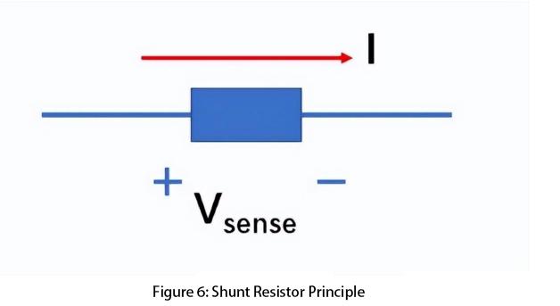
Shunt resistor: A shunt resistor is a precision resistor with very low resistance. The resistance is small enough that the voltage drop across the shunt resistor in high-power current paths within the battery system can be negligible, yet large enough to be accurately measured by the battery management system. The schematic diagram of a shunt resistor is shown in Figure 6.
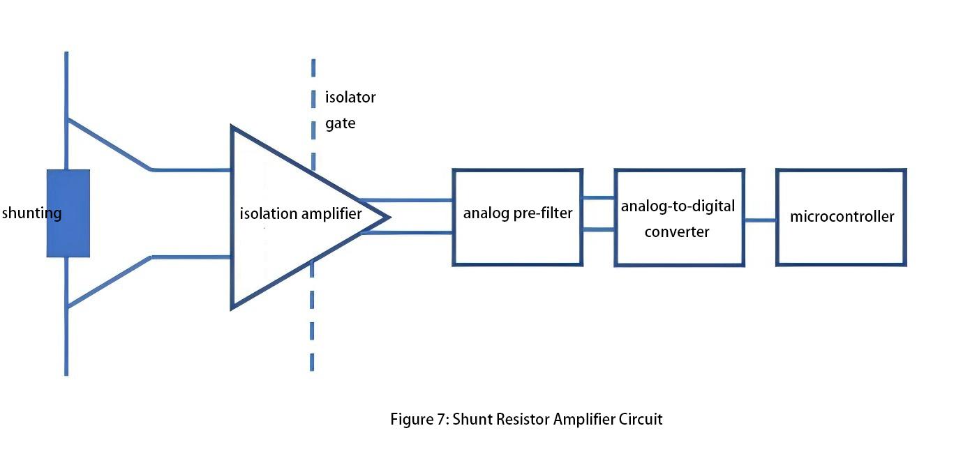
The shunt resistor is inexpensive, comes in a variety of types, and does not require an external power source. Typically, the measurement accuracy of a shunt resistor can reach 0.1% to 0.5%. Additionally, the shunt resistor amplifier circuit requires high common-mode rejection ratio, low DC offset, high gain, and good thermal stability (see Figure 7). For systems operating over a wide temperature range, the battery management system must consider the variation of shunt resistor resistance with temperature.
Hall Effect Sensor: The Hall effect is the generation of a voltage proportional to the current in the presence of a magnetic field. Unlike shunt resistors, Hall effect sensors require external power supply. There are two types of Hall effect sensors: open-loop and closed-loop. The closed-loop type includes an additional coil around the magnetic core. By controlling the current magnitude and direction in this coil, the total magnetic flux in the core can be set to zero, proportional to the desired current and battery current. Closed-loop sensors offer higher accuracy and response time, are less prone to magnetic saturation, but are larger in size and higher in cost.
Most Hall effect sensors exhibit zero offset error, which varies with temperature. Such errors significantly affect State of Charge (SOC) calculations using Coulomb counting. For instance, a current sensor with an offset error of 0.001C will accumulate a 16.8% SOC error after one week of operation. Therefore, zero-drift compensation and zero-current elimination are used in Hall effect sensors to mitigate the impact of zero offset error.
current and voltage synchronization
When the BMS system evaluates the operational status of battery cells, it requires synchronized data acquisition of voltage and current. The simplest method for synchronizing current and voltage acquisition is to measure all voltages and currents within a very short time frame, minimizing differences to negligible levels. Additionally, incorporating timestamps into measurement devices ensures accurate battery state estimation.
temperature measurement
The BMS plays a critical role in thermal management based on the core temperature to ensure it operates within the specified temperature range, while also controlling the temperature difference within the same battery stack or cluster. Thermistors are one of the most common devices used in embedded systems for temperature measurement.
The resistance of a thermistor changes with temperature, classified into negative temperature coefficient (NTC), where the resistance increases as the temperature decreases, and positive temperature coefficient (PTC), where the resistance increases with temperature rise.
Under normal conditions, lithium-ion batteries operate within the range of -5°C to 35°C. It requires high accuracy in thermistor measurement within this range because cells may experience thermal runaway and other anomalies. Therefore, thermistors must have a wide measurement range, although measurement precision can be reduced outside this temperature range. In the design of temperature measurement, the following aspects should be considered:
1. What is the difference in the measured highest/lowest voltage in the battery system and the actual highest/lowest voltage of the cells? Because batteries themselves may have thermal gradients, it is necessary to measure this actual maximum difference under various experimental conditions.
2. How much lower is the measured temperature compared to the core temperature of the cells during maximum power charging and discharging scenarios? BMS temperature measurement is typically limited to the battery surface temperature, while there exists a difference between the internal cell temperature and the battery surface temperature. In extreme cases, it is necessary to determine whether the internal cell temperature exceeds the safe temperature range, requiring detailed verification under various laboratory conditions.
3. A scenario to consider is when an individual cell may experience an internal short circuit, leading to temperature rise and even entering a thermal runaway state. The BMS needs to quickly identify such faults based on temperature rise rates, temperature ranges, and other indicators, thereby promptly isolating the fault.
Contactor Control
In a Battery Management System (BMS), contactor control serves a critical function. If the contactor fails to operate correctly, it cannot interrupt the current during abnormal conditions, thereby failing to prevent battery overcharging and overdischarging. The BMS needs the capability to detect contactor failures, including failure to open and failure to close. Contactor welding, which prevents disconnection, poses a potential threat.
Each contactor has its rated maximum lifespan, which denotes the maximum number of cycles it can endure under various switching conditions.
Soft start and pre-charge circuit
In multi-branch energy storage systems, the BCMU requires circuits with soft start or pre-charge functions to mitigate large circulating currents caused by significant voltage differentials between different clusters paralleled on the same bus. Such circulating currents can cause significant damage to contactors.
Typically, contactors should close under a smaller voltage differential, and current should only flow after the contacts are fully closed. The most common solution to address such issues is to use a soft start circuit (see Figure 8). This circuit utilizes a resistor and an additional contactor connected in series, which is then paralleled with a main contactor.
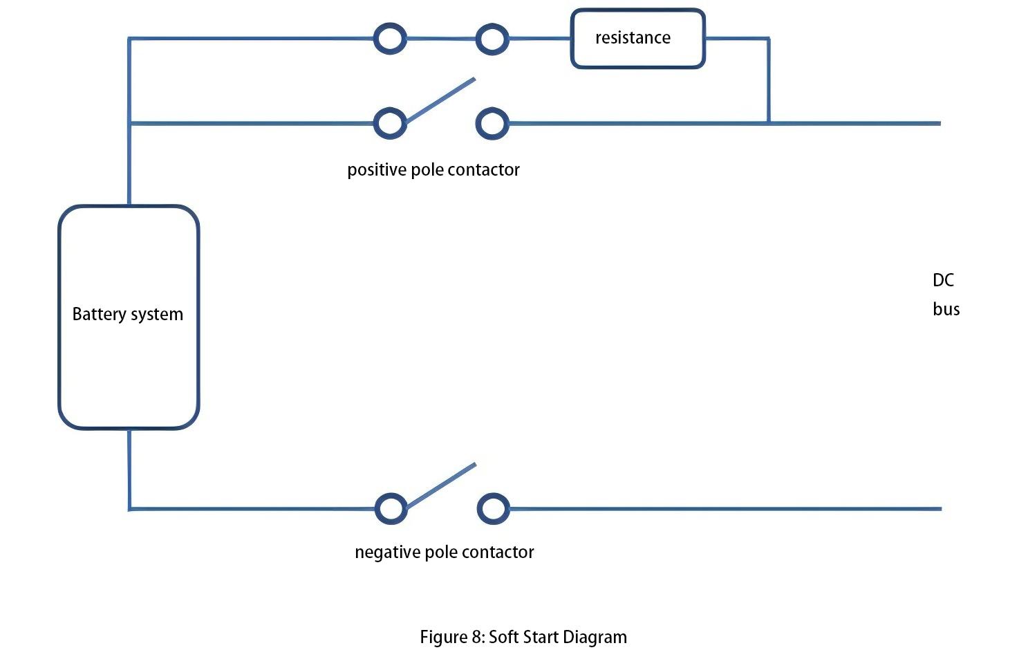
When the battery system is ready to connect to the DC bus, the branch contactors close to limit the current within a reasonable range through the resistor in the pre-charge circuit. As the battery system voltage gradually rises and the voltage difference with the DC bus becomes sufficient, closing the main contactor effectively short-circuits the pre-charge circuit, after which the contactor of the pre-charge circuit is reopened.
To enhance system reliability, BMS uses multiple contactors. If one contactor becomes welded, the second contactor can provide an effective isolation method.
Detection of contactor faults
Contactor fault detection generally employs two methods. One method involves measuring the actual high-voltage system to determine whether there is a conductive path between the two sides of the contactor. The other method is to install auxiliary contacts. Typically, the strategy with auxiliary contacts requires additional inputs and wiring, leading to more fault modes associated with improper operation of the auxiliary contacts. The high-voltage measurement method can directly detect the current status of the contactor circuit and has higher fault tolerance capabilities.
Determining contactor faults involves making a logical assessment based on the open/close status returned by the contactor and the current/voltage measurements within the battery cluster.
Thermal management system
No matter whether it is the available capacity of the battery, the degree of degradation of the cells during cycling, or the temperature during the operation of the cells, energy storage systems will be equipped with cooling methods such as air cooling, liquid cooling, and immersion cooling. However, regardless of the cooling method used, the goals are twofold.
On one hand, minimizing the temperature difference within the same cluster of cells is preferable (series arrangement), aiming to achieve uniform cell degradation within the cluster. On the other hand, maintaining an average temperature of around 25 degrees Celsius for the entire cluster of cells with minimal deviation is ideal, approximating the operating environment of the cells to laboratory testing conditions. Additionally, the thermal management system must consider its power consumption, as all power consumed contributes to the self-use power of the energy storage system; excessive power consumption can adversely affect the efficiency of the entire energy storage system.
Therefore, when designing strategies for thermal management, it is necessary to find a balance point where cooling achieves both objectives with minimal self-use power. For air cooling systems, reducing the number of cells within each module as much as possible is recommended to better control temperature variations of each cell. For example, using 280Ah cells, configuring 8 cells per module and equipping each module with individual BMUs and fans can control the temperature difference within each module to within 5 degrees Celsius.
Electromagnetic Compatibility
In a large-scale energy storage system, there exists a highly complex electromagnetic environment, with one significant source of interference being the carrier waves from multiple parallel operating PCS systems. Asynchronous carrier waves can cause high-frequency interference that feedbacks through DC-side grounding capacitors to the battery side. The peak-to-peak value of this interference can reach thousands of volts.
Maintaining precise voltage and temperature measurements of battery cells for the BMS in such a strong electromagnetic interference environment poses a challenge. Ideally, the low-voltage and high-voltage systems operate independently without interference. However, in practical operation, low currents can still pass through isolation devices. This necessitates rigorous EMC testing for the BMS.
Insulation detection
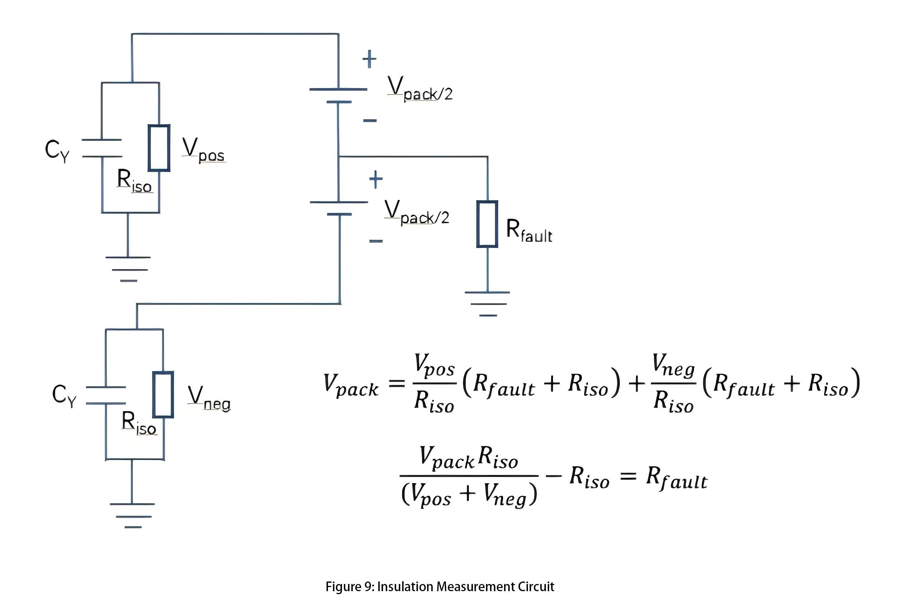
In energy storage systems, there are parasitic capacitances and conductances between insulation high-voltage components like battery modules and ground/chassis. These parasitic components require special consideration. Therefore, insulation detection circuits, either offline or online, should be integrated into the battery management system. Figure 9 provides a simple illustration of an insulation detection circuit.
The Rfault value can be calculated from two measurements. For each measurement, the known resistance Riso is plugged in between the ground and the positive and negative stages of the battery, and the voltage across the resistance is measured. When the measuring resistance Riso is connected, it and the Y-capacitor form an RC circuit. The capacitor must be filled before the measurement can be made. This determines the minimum time required to make this measurement.
BMS software component
Battery model
In battery management systems, the purpose of battery modeling is to create a representation that uses easily measurable physical quantities (such as voltage, temperature, and current) to calculate physical quantities that cannot be directly measured (such as State of Charge - SOC and State of Health - SOH).
For lithium-ion batteries, there exists a one-to-one relationship between the open circuit voltage (Voc) of lithium ions and SOC, which can be represented by the SOC-OCV curve. This curve enables the real-time calculation of the battery's open circuit voltage (Voc) through the battery model, thereby allowing measurement of the real-time SOC of the battery.
However, in practical measurement processes, batteries exhibit noticeable hysteresis. A classic experiment involves using identical batteries, one fully charged and one fully discharged, approaching approximately equal SOC values from opposite directions, yet their measured voltages are not equal.
During charging and discharging processes, distinct SOC-OCV curves are generated for charging and discharging. In practical applications, a curve is typically drawn between these charging and discharging curves to approximate the zero-lag voltage for a given SOC.
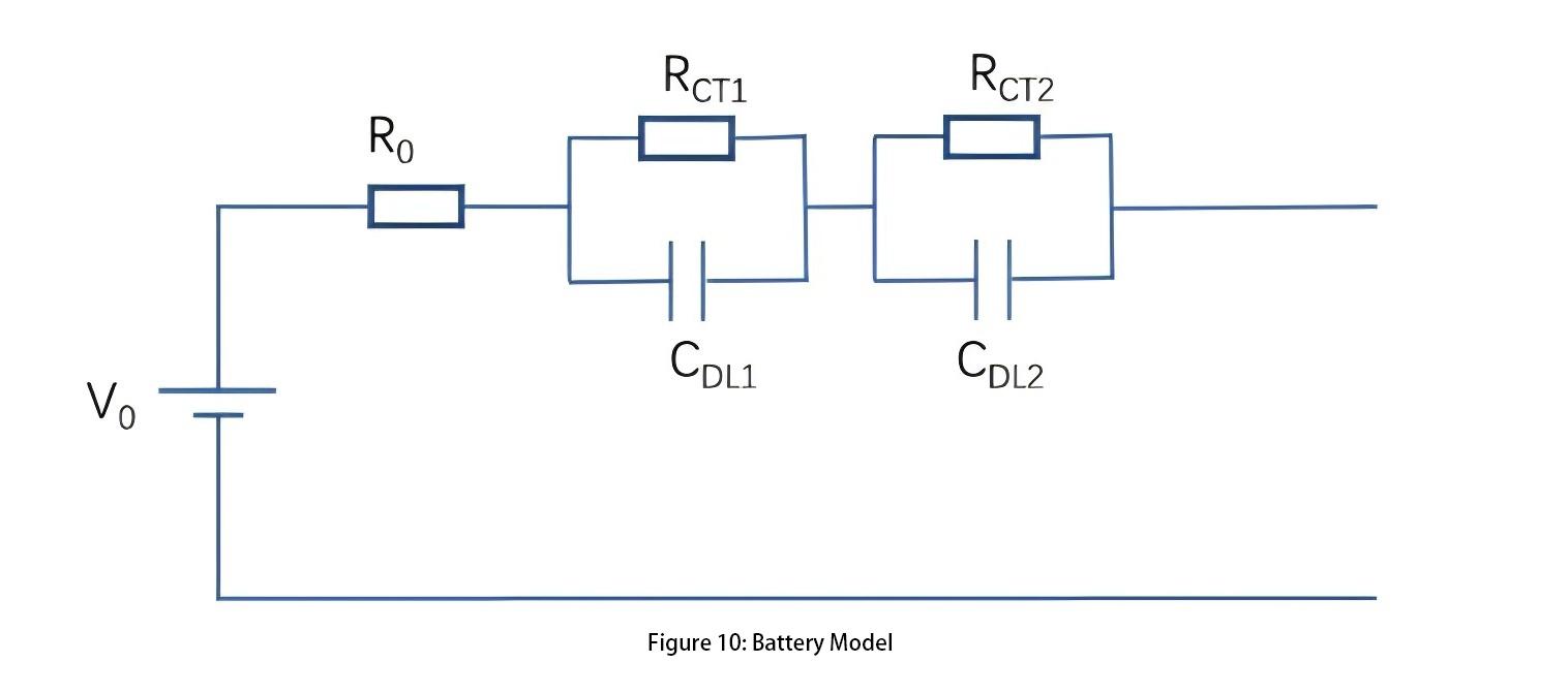
When a battery undergoes regular charging and discharging currents, its external characteristics do not exhibit purely linear resistor behavior. Therefore, based on the step and impulse responses exhibited by the battery, a second-order model of the battery can be derived, as illustrated in Figure 10.
For battery models, accurately determining the parameters of the battery model is crucial, as it will be elaborated in the subsequent parameter identification algorithms.
Parameter identification
In adaptive model parameterization, model parameters are determined based on the relationship between current and voltage. This involves continuously adjusting the model parameters so that the model output of current and voltage matches the actual measured current/voltage curve. The most typical algorithm used for parameter identification is recursive least squares.
By observing a series of data points from battery testing, actual measured current values are input into the model. Through model calculations, voltage values can be obtained. The error between the model-predicted voltage and the actually measured voltage is a crucial criterion for assessing the quality of the model.
The objective is to find a set of model parameters that minimize this error. Therefore, this error function serves as the objective function. Each iteration involves taking the derivative of the objective function with respect to each parameter and continuously updating the model parameter values until the desired effect is achieved.
For battery cells, parameter identification methods can be used to determine the operational status by evaluating whether the internal impedance values are within reasonable ranges. Classifying battery cell health into categories such as healthy, sub-healthy, fault warning, and fault states based on these parameter levels allows for timely replacement of cells nearing failure, thereby preventing major accidents.
Determining the safe operating region of energy storage systems
Based on the operational characteristics of the battery cells, the Battery Management System (BMS) needs to delineate the safe operating region for the energy storage system. If this region is overly conservative, the performance of the energy storage system may not be fully utilized, affecting its economic viability. Conversely, if the region is too aggressive, it could accelerate degradation of the energy storage system and even threaten its safe operation. Several key pieces of information are used to define the safe operating region of the entire energy storage system:
1. Individual Cell Voltage Range: What are the maximum and minimum voltage values within which individual cells can operate?
2. Individual Cell Temperature: What is the upper limit for normal operation temperature? What is the critical temperature at which thermal runaway and other destructive effects begin to occur? Given the specific thermal management system, what is the maximum charge/discharge current to maintain cell temperatures within a reasonable range?
3. Maximum Charge/Discharge Current: What is the maximum charge/discharge rate of the battery? Under constant power operation, what are the maximum charge/discharge current values and terminal voltage that can determine the maximum achievable charge/discharge power output of the energy storage system?
4. Critical Voltage Change Rate during Standard Charge/Discharge: What is the voltage change rate that reflects State of Health (SOH) and other fault information during standard charging and discharging?
5. Critical Temperature Change Rate during Standard Charge/Discharge: What is the temperature change rate during standard charging and discharging?
6. State of Charge (SOC): What is the Depth of Discharge (DoD) of the cells? What is the balancing strategy?
Since the energy storage system comprises numerous cells connected in series and parallel, it exhibits the "weakest link" effect. This means the performance of the entire battery pack is limit
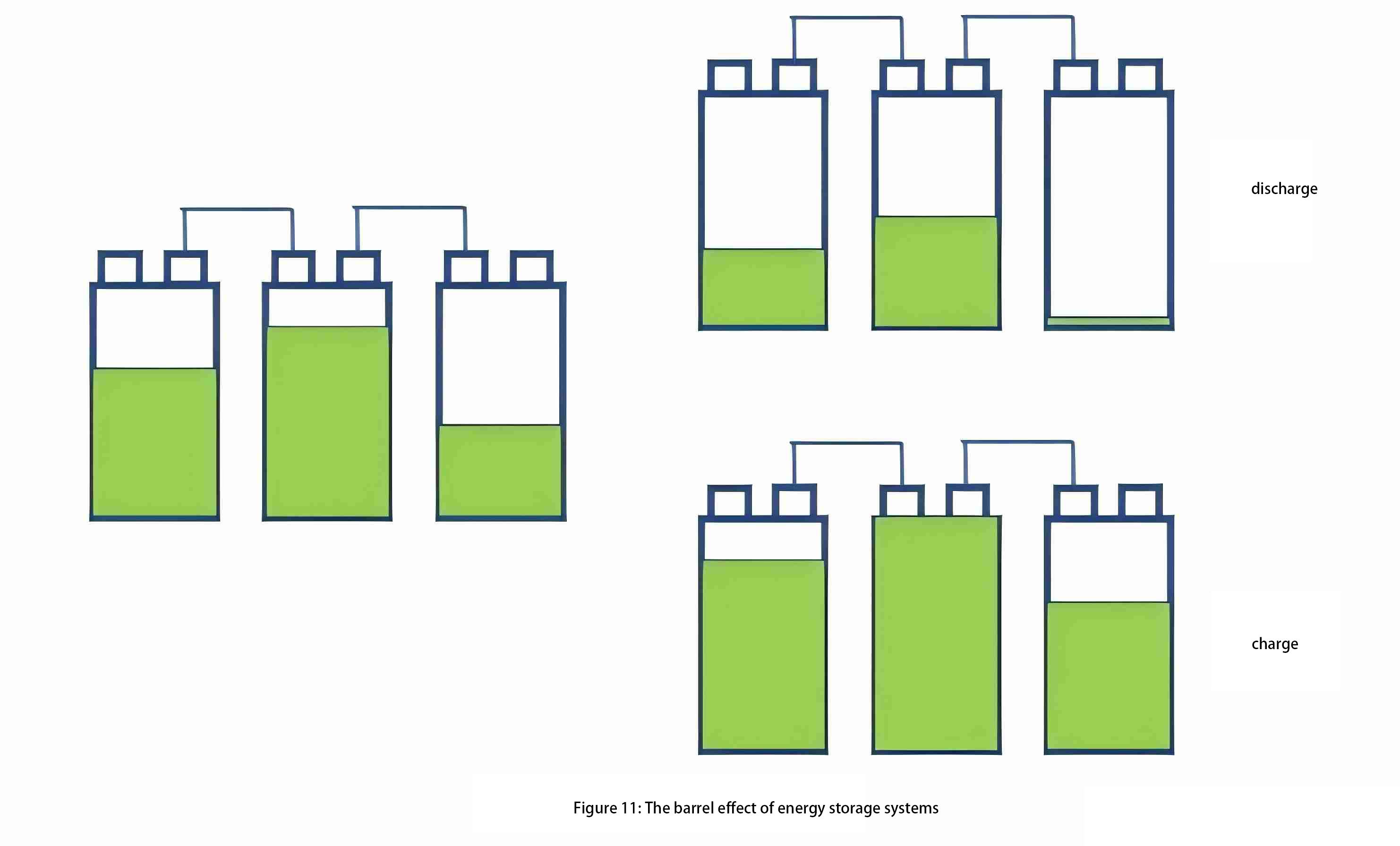
As shown in Figure 11, when the SOH (State of Health) of battery cells is consistent (same capacity), but the SOC (State of Charge) varies (different remaining charge), during the charging process, once the middle cell in a series cluster reaches full charge, the entire series cluster cannot continue charging even if the other cells are not fully charged.
During discharge, after the rightmost cell in the cluster is depleted, the remaining cells in the same cluster also cannot continue discharging. This phenomenon is known as the "barrel effect" in energy storage systems, caused by unevenness in series and parallel connections.
One of the core objectives in integrating energy storage systems is to reduce the impact of this barrel effect, aiming to extend the system's cycle life close to that of individual battery cells.
To address imbalance issues in energy storage systems, balancing methods through Battery Management Systems (BMS) can be employed. Balancing strategies in BMS can be categorized into active balancing and passive balancing. Active balancing strategies include:
Capacitive balancing circuits:
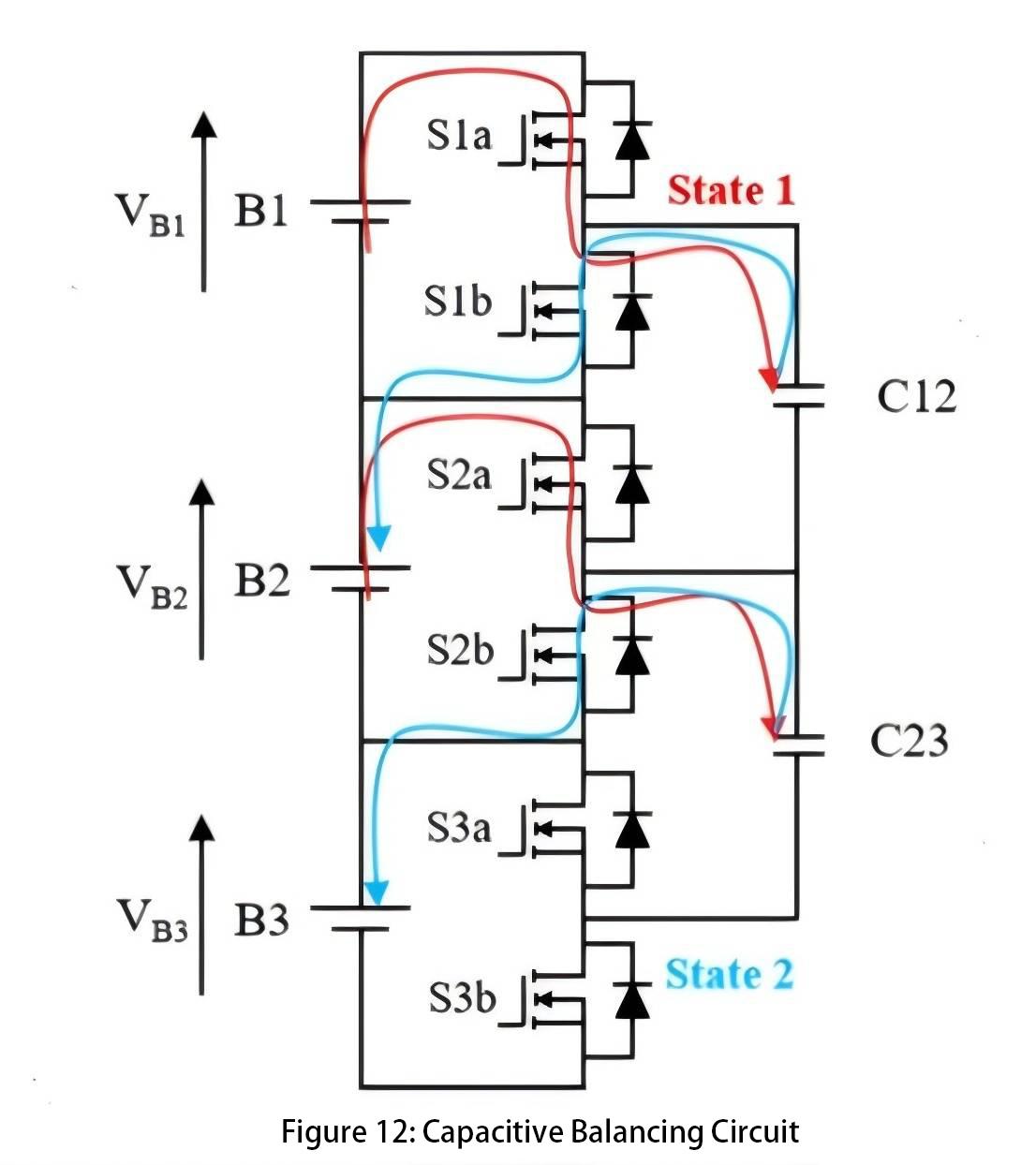
Figure 12 shows a capacitive balancing circuit where, with S1a closed, cell 1 charges capacitor C12. After closing S1a, S1b is closed, allowing capacitor C12 to charge cell 2. This facilitates the transfer of charge between cells using capacitors to balance the uneven charge levels among the cells. Such a balancing circuit can only transfer charge from cells with higher voltage to cells with lower voltage.
However, in practical applications, we prefer balancing based on SOC values. Some cells, due to lower capacity, experience rapid voltage changes; their voltage may be high at one moment but drop quickly afterward. In such cases, we do not want to transfer charge. Additionally, incorrect switch sequences can lead to safety issues.
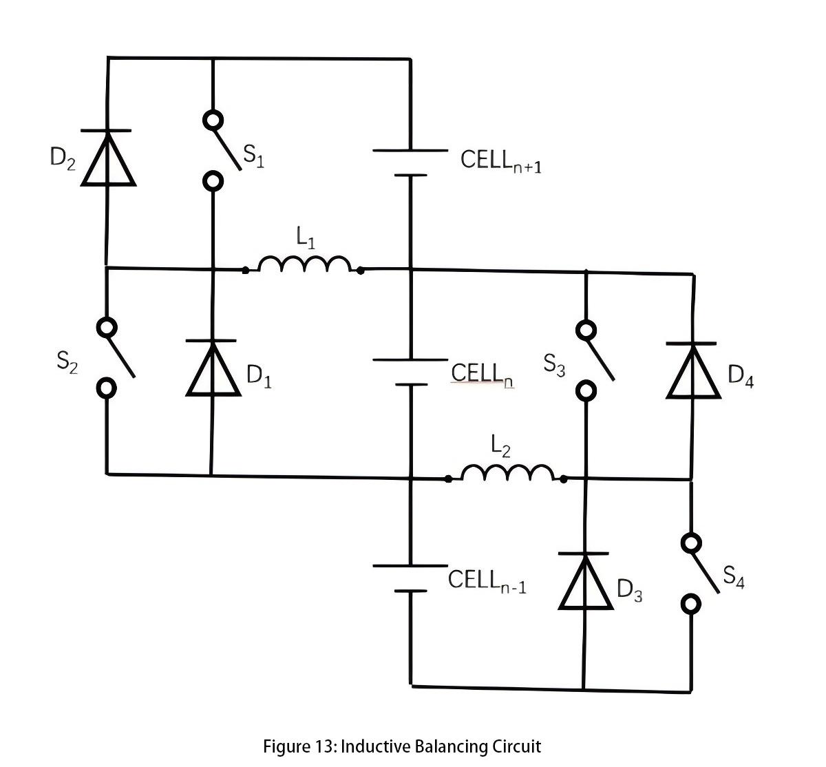
Inductive Balancing Circuit (Figure 13):
During the balancing process, charge can be transferred from cell n+1 to cell n. Closing switch S1 allows cell n+1 to charge inductor L1, storing energy in the inductor. When S1 is opened, current flows through diode D1 to charge cell n. To transfer charge from cell n to cell n+1, control switch S2 is activated.
This method does not require cell n+1 to have a higher voltage than cell n, nor is it restricted by voltage differences. Proper selection of inductor size and switch frequency is essential to achieve the desired balancing current without saturating the inductor. However, the main drawback of this circuit is that it can only transfer energy between adjacent cells. Efficiency decreases significantly when transferring energy among a large number of cells.
DC/DC Balancing Circuit (Figure 14):
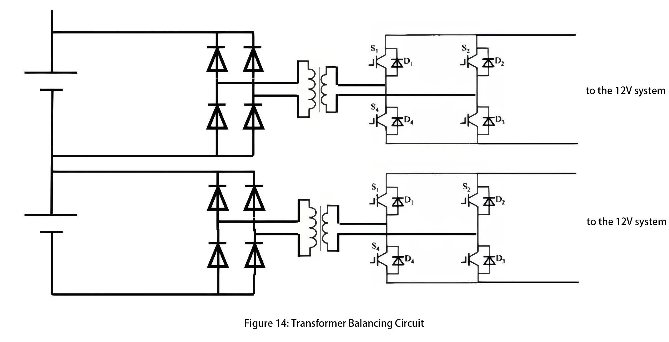
Through isolated DC/DC circuits, individual batteries can transfer energy to another battery. This architecture enables balancing between any two cells within the same cluster. In practical applications, cell selection units are often integrated to reduce the number of DC/DC modules and overall costs.
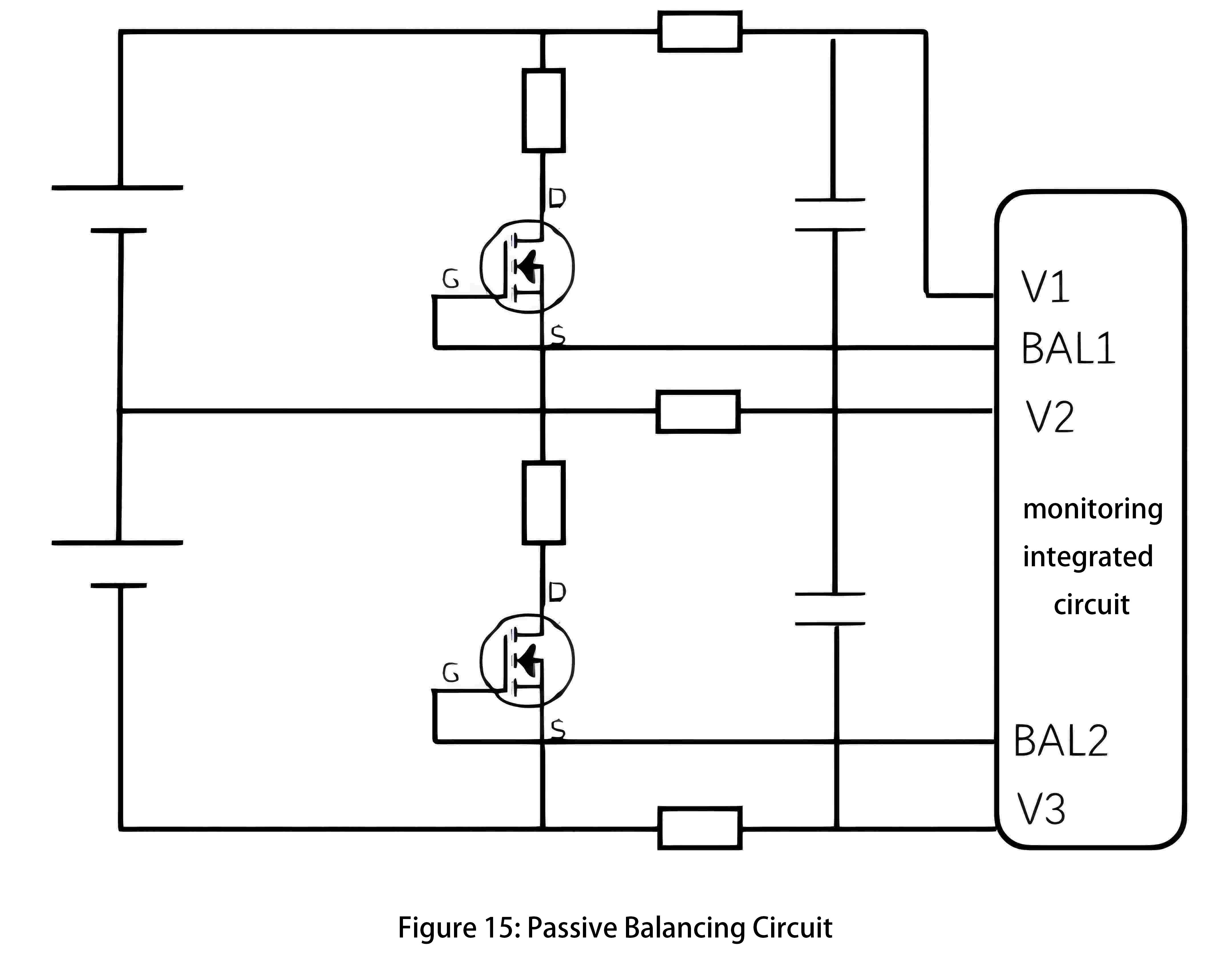
Passive Balancing Circuit: The main principle of a passive balancing circuit is to automatically discharge cells with higher remaining charge through resistors, thereby reducing their charge and equalizing their levels with other cells. Modern Analog Front End (AFE) monitoring ICs typically include built-in passive balancing functionality, as illustrated in Figure 15.
The AFE chip can output a BAL signal to control the switching of MOSFETs, thereby balancing individual battery cells. Careful selection of balancing resistors is essential; using PCB surface-mount resistors, for instance, results in the highest heat dissipation among components. Passive balancing circuits are simple in structure and cost-effective, but their balancing effectiveness is generally inferior to that of active balancing circuits.
Battery State of Charge (SOC) calculation
SOC (State of Charge) mainly refers to the ratio of the current charge (in Coulombs) available in a battery to its total charge capacity when fully charged. It is important to note that SOC and State of Energy (SOE) are distinct concepts, with SOE representing the area under the charge-discharge curve.
When calculating SOC, the following aspects need to be considered:
1. Coulomb efficiency: The Coulomb efficiency of lithium-ion batteries is typically around 99%. Therefore, formulas for charge and discharge incorporate the Coulomb efficiency factor.
2. Variation in battery terminal voltage: During actual charge and discharge processes, a battery's terminal voltage does not behave like an ideal voltage source; it fluctuates continuously. Thus, the State of Energy (SOE) is inconsistent at the same time interval.
3. Capacity variation with temperature: Battery capacity exhibits a nonlinear relationship with temperature.
4. Capacity variation with charge and discharge rates: At higher discharge rates, a battery's capacity decreases.
The inconsistency between the fully charged and fully discharged curves is mainly due to polarization and hysteresis effects. Due to the influence of these factors and others, achieving precise SOC calculation (with an error rate less than 3%) is a significant challenge. There are various existing methods for calculating SOC, including ampere-hour integration, open circuit voltage (OCV) curve, Kalman filtering, and various AI algorithms.
The ampere-hour integration method relies heavily on the accuracy of current measurements. Errors accumulate continuously due to the integration algorithm, and an initial SOC value is required. However, ampere-hour integration provides precise short-term calculations and serves as a useful benchmark for other algorithms. This method does not account for temperature effects on SOC; therefore, a temperature correction factor is often added based on ampere-hour integration.
The OCV curve method requires the battery to be in a rested state for several hours, after which the SOC-OCV curve is consulted to determine SOC. Typically, deviations of around 10mV during the charge-discharge plateau can lead to approximately 30% SOC error. This method is commonly used to correct the initial SOC value in ampere-hour integration methods.
Kalman filtering is based on battery model state estimation to calculate SOC. It utilizes measured voltage and current to estimate open circuit voltage (OCV), which is then used with the SOC-OCV curve to determine SOC. Extended Kalman filtering (EKF) and Unscented Kalman filtering (UKF) are used for SOC estimation in battery systems. UKF avoids the calculation of Jacobian matrices compared to EKF, thus providing more accurate SOC values. Kalman filtering is not affected by initial value errors and minimizes memory requirements, making it suitable for embedded systems.
Various AI algorithms utilize data from fully charged and discharged battery cycles to train structures such as neural networks for real-time SOC calculation. This method offers high accuracy in SOC estimation but requires extensive training data and complex calibration processes. However, it is considered a promising direction for development.
Remaining Capacity State of Health (SOH) calculation
The capacity of a cell will degrade over time with the number of charge/discharge cycles and total operating time. The State of Health (SOH) of a battery is primarily related to its effective capacity, impedance, and self-discharge rate. For calculating SOH, an approximate function can be established to model capacity degradation. For instance, the capacity of a battery during cycle k can be expressed as a function of the following parameters:
- Capacity in the previous cycle C(k-1)
- Temperature during cycle k-1 T(k-1)
- Charge/discharge current during cycle k-1 I(k-1)
- State of Charge (SOC) during cycle k-1 SOC(k-1)
- Duration of cycle k-1 t(k-1)
- Initial capacity C0
- Total operating time t(k)
Various time series prediction algorithms can be utilized with historical data to estimate the actual SOH value.
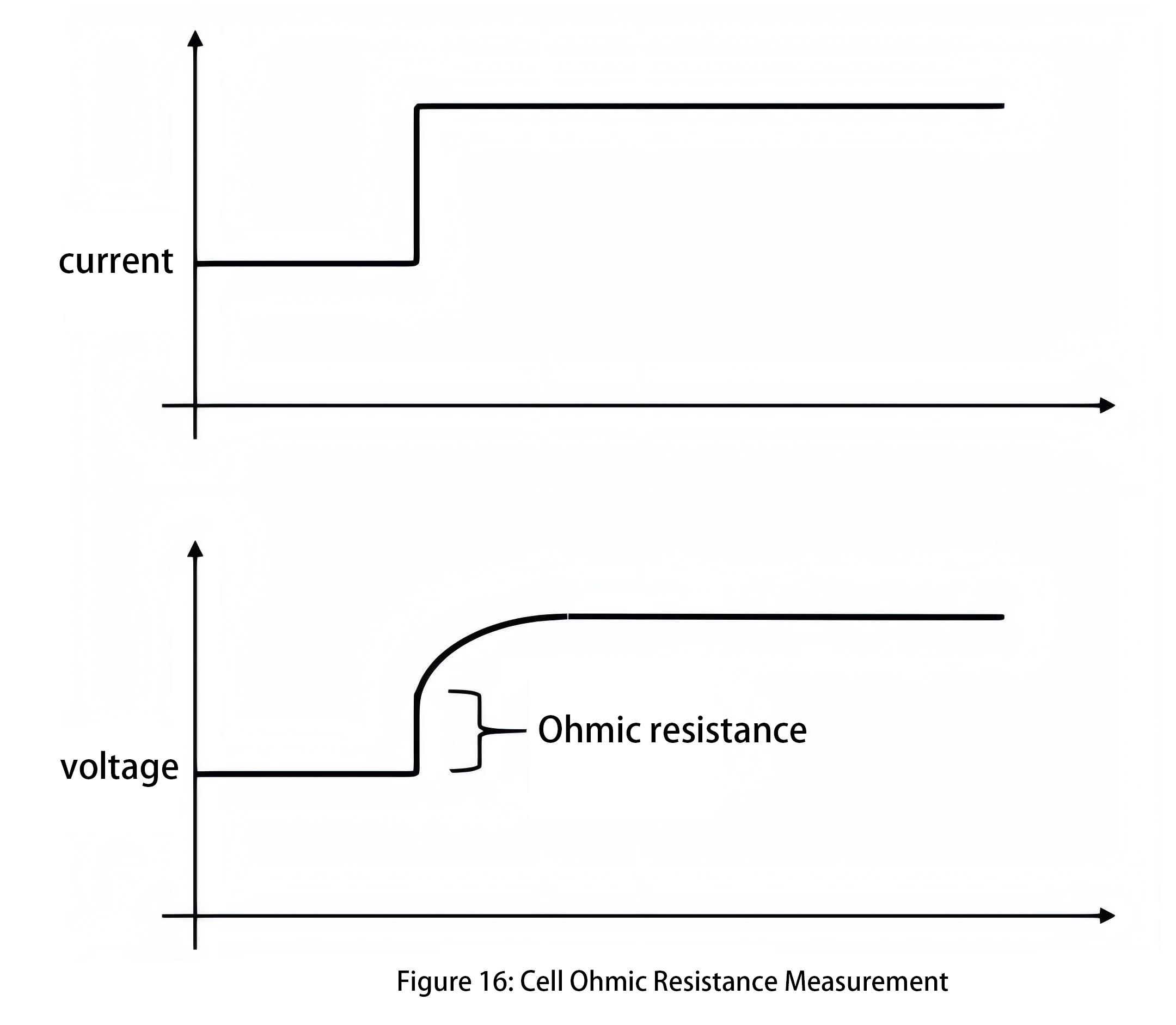
Furthermore, SOH is related to internal impedance values, which can be estimated by testing internal impedance to approximate SOH. Linear least squares fitting can be employed to fit a series of ordered pairs of voltage and current, providing a relatively accurate estimate of DC Ohmic resistance. The slope of the regression line obtained by least squares regression equals the impedance, while the intercept of the regression line represents the non-IR voltage value. Additionally, approximate values of step changes in current can detect corresponding transient voltage changes. The ratio of DeltaV/DeltaI can be used to calculate the Ohmic resistance at that point, as shown in Figure 16.
For large-scale energy storage systems, they typically operate through full charge and full discharge cycles, which effectively estimate the available capacity of the cells. However, the available capacity of cells is temperature-dependent. Therefore, when assessing capacity changes, it's preferable to conduct full charge and full discharge cycles at consistent temperatures or use temperature calibration factors to adjust capacity values.
operating mode
The BMS system employs one or more finite state machine algorithms responsible for controlling the battery's operational states. These state machines respond to external commands and monitor various internal conditions of the battery system. Typically, the battery system operates in "low power" or "sleep" mode. In this mode, the system minimizes power consumption from the high-voltage battery pack control to reduce cell inconsistency.
Even when the battery system is not actively running, it is essential to periodically wake the BMS from sleep mode. This is necessary for more accurate estimation of state of charge (SOC) and for appropriate cell balancing. Additionally, it allows for detection of various battery defects, including self-discharge.
summary
Battery Management Systems (BMS) for large-scale energy storage systems are highly complex systems that need to consider various failure conditions of the energy storage system and respond with appropriate protective actions, ensuring the system operates within a reasonable and safe range.
The design of a Battery Management System can be divided into hardware and software components. The hardware components include embedded acquisition circuits, main control circuits, balancing circuits, as well as electrical devices such as circuit breakers and contactors. Among these, the precision of cell voltage and temperature acquisition is crucial, as it provides the fundamental data for the software and forms the basis for protective actions.
The software part includes calculations of cell State of Charge (SOC) and State of Health (SOH), and intelligent analysis of cell status. SOC and SOH values provide the basis for cell balancing, and the accuracy of SOC/SOH calculations affects the balancing efficiency of the energy storage system.
The effectiveness of cell balancing in an energy storage system determines how closely its cycle life approaches that of the individual cells. Therefore, the hardware and software of the BMS are complementary components of a systematic engineering approach, requiring in-depth analysis of cell operating characteristics. Starting from top-level design, every detail must be carefully considered to achieve an efficient and reliable battery management system.