Details
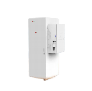
High Voltage All-In-One Hybrid ESS 30KW/50KWh Battery Energy Storage Flexible All-in-one design and highly integrated Modular design with different optional parts Easy-to-install IP54 Parallel installation side-by-side or back-to-back. Comp
Description

 FlexibleEasy-to-installComplianceCompatible
| Model | SUN-30K-SG01HP3-EU-BM3 | Notes |
| Battery Input Data | ||
| Battery Type | Lithium-ion | |
| Battery Voltage Range (V) | 160-800 | |
| Max. Charging Current (A) | 50+50 | |
| Max. Discharging Current (A) | 50+50 | |
| Charging Strategy for Li-ion Battery | Self-adaption to BMS | |
| Number of Battery Input | 2 | |
| PV String Input Data | ||
| Max. DC Input Power (W) | 39000 | |
| Max. DC Input Voltage (V) | 1000 | |
| Start-up Voltage (V) | 180 | |
| MPPT Voltage Range (V) | 150-850 | |
| Rated DC Input Voltage (V) | 600 | |
| Max. Operating PV Input Current (A) | 36+36+36 | |
| Max. Input Short-Circuit Current (A) | 55+55+55 | |
|
No. of MPP Trackers/ No. of Strings per MPP Tracker |
3/2+2+2 | |
| AC Input/Output Data | ||
| Rated AC Input/Output Active Power (W) | 30000 | |
| Max. AC Input/Output Apparent Power (VA) | 33000 | |
| Rated AC Input/Output Current (A) | 45.5/43.5 | |
| Max. AC Input/Output Current (A) | 50/47.9 | |
| Max. Three-phase Unbalanced Output Current (A) | 60 | |
| Max. Continuous AC Passthrough (grid to load) (A) | 200 | |
| Peak Power (off-grid) (W) | 1.5 times of rated power, 10s | |
| Power Factor Adjustment Range | 0.8 leading to 0.8 lagging | |
| Rated Input/Output Voltage/Range (V) | 220/380V, 230/400V 0.85Un-1.1Un | |
| Rated Input/Output Grid Frequency/Range(Hz) | 50/45-55, 60/55-65 | |
| Grid Connection Form | 3L+N+PE | |
| Total Current Harmonic Distortion THDi | <3% (of nominal power) | |
| DC Injection Current | <0.5% In | |
| Efficiency | ||
| Max. Efficiency | 97.60% | |
| Euro Efficiency | 97.0% | |
| MPPTEfficiency | >99% | |
| Equipment Protection | ||
|
Integrated |
DC Polarity Reverse Connection Protection, AC Output Overcurrent Protection AC Output Overvoltage Protection, AC Output Short Circuit Protection, Thermal Protection DC Terminal Insulation Impedance Monitoring, DC Component Monitoring, Ground Fault Current Monitoring Power Network Monitoring, Island Protection Monitoring, Earth Fault Detection, DC Input Switch Overvoltage Load Drop Protection, Residual Current (RCD) Detection, Surge protection level |
|
| Surge Protection Level | TYPE II(DC), TYPE II(AC) | |
| Interface | ||
| Communication Interface | WIFI, RS485, CAN | |
| General Data | ||
| Operating Temperature Range (℃) | -40 to +60℃, >45℃ Derating | |
| Permissible Ambient Humidity | 0-100% | |
| Permissible Altitude | 2000m | |
| Noise (dB) | ≤65 | |
| Ingress Protection(IP) Rating | IP 65 | |
| Inverter Topology | Non-Isolated | |
| Over Voltage Category | OVC II(DC), OVC III(AC) | |
| Cabinet Size (WxHxD mm) | 527×894×294 (Excluding Connectors and Brackets) | |
| Weight (kg) | 80 | |
| Type of Cooling | Intelligent Air Cooling | |
| Warranty |
3Years/5 Years/10 Years the Warranty Period Depends the Final Installation Site of Inverter, More Info Please Refer to Warranty Policy |
|
| Grid Regulation | IEC 61727, IEC 62116,CEI 0-21, EN 50549, NRS 097, RD 140, UNE 217002, OVE-Richtlinie R25, G99,VDE-AR-N 4105 | |
| Safety / EMC Standard | IEC/EN 61000-6-1/2/3/4, IEC/EN 62109-1, IEC/EN 62109-2 | |
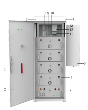
| NO | Name | NO | Name |
| 1 | Aerosol fire extinguishing device | 8 | Air conditioning circuit breaker |
| 2 | Energy storage cabinet | 9 | Control system circuit breaker |
| 3 | Smoke detector | 10 | Electricity meter |
| 4 | Energy storage battery | 11 | EMS |
| 5 | Heat detector | 12 | Surge circuit breaker |
| 6 | PCS | 13 | Lightning arrester |
| 7 | High pressure box |

| NO | Name | NO | Name |
| 1 | Battery Module (51.2V280Ah) | 5 | B- |
| 2 | Battery box | 6 | B+ |
| 3 | BMS | 7 | Fan |
| 4 | Communication port | 8 | Aluminum strip |
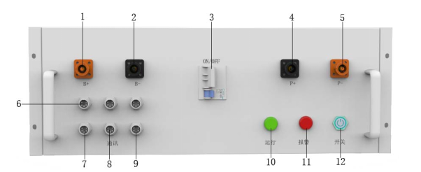
| NO | Name | NO | Name |
| 1 | B+ | 7 | Battery communication |
| 2 | B- | 8 | BMS communication |
| 3 | Air switch | 9 | PCS communication |
| 4 | P- | 10 | Running indicator light |
| 5 | P+ | 11 | Alarm indicator light |
| 6 | Upper computer communication | 12 | Switch |